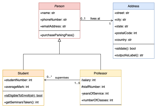

UML class diagrams are used to illustrate the structure of a computer program. They detail the types of data or attributes stored within each ‘class’, the methods (operations or functions) that each class provides, and the relationships between the classes.
Class diagrams are likely the most common and important type of UML diagram.
While they commonly document an existing application, you may find your team creates cleaner code when you draw a class diagram before any implementation starts.
Do UML class diagrams need to be detailed?
Accurate and detailed class diagrams are important when changing an existing application, or re-implementing it in another programming language. Specification and implementation details are useful when multiple teams work on the same program.
You can create rough class diagrams using just the names of the classes and drawing their relationships. Use this conceptual level of detail to get feedback on ideas.
While UML has a well-defined notation, you can ‘relax the rules’ in rough class diagrams.
On this page
The shapes you need to create class diagrams are in the two UML shape libraries.
Enable the UML shape libraries
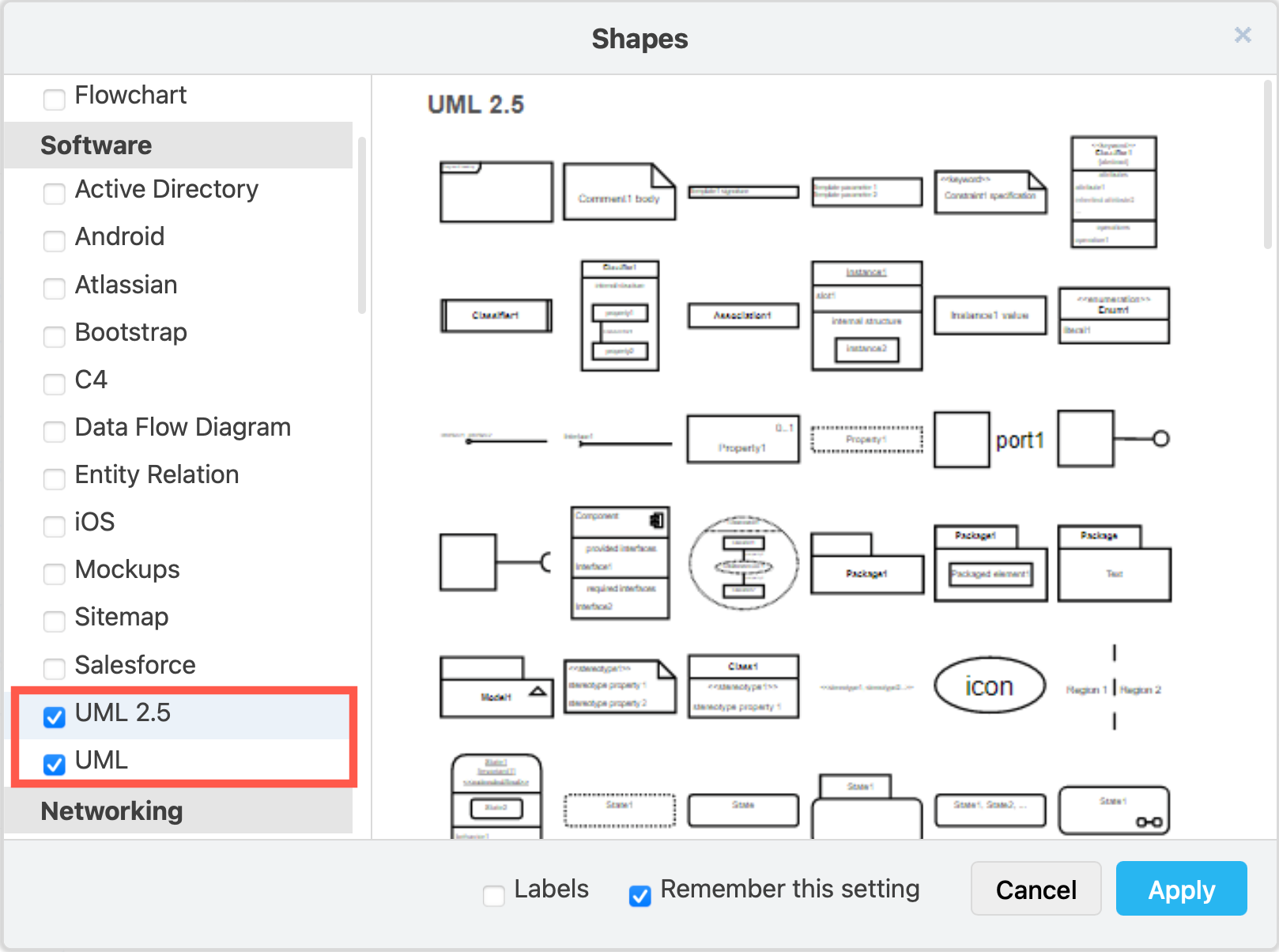
Most class shapes are in the main UML shape library. Hover over any shape in the shape library to see a larger preview.
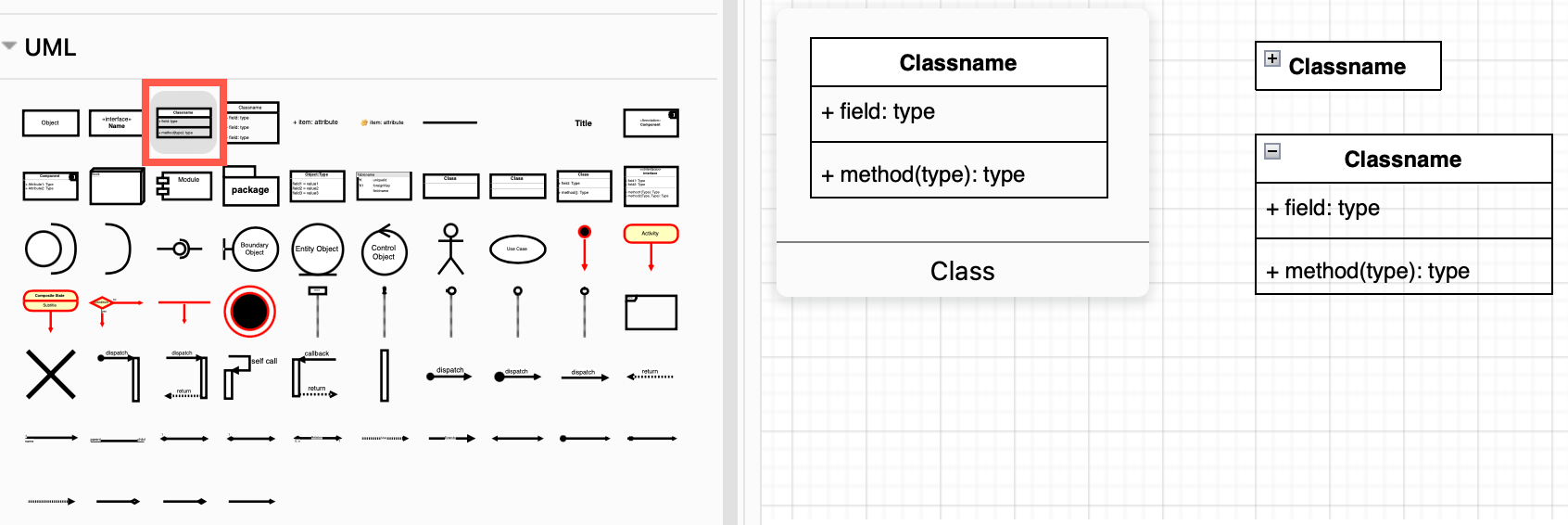 The first few class shapes in the UML shape library are collapsible" width="" height="" />
Tip: The first two class shapes in the UML shape library are collapsible, making it easy to simplify a complex diagram without recreating it from scratch.
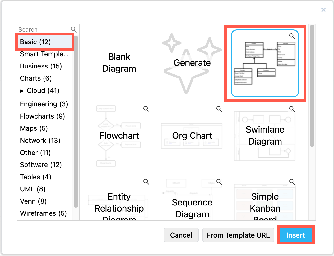
Use a template or example class diagram
UML class shapes always have a Class Name .
Classes in detailed diagrams have two additional sections for attributes and methods, and usually follow the UML notation, detailed in the sections below.
Detailed UML classes are separated into three sections with the class name at the top.
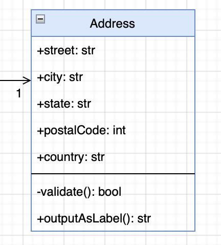
Parameter names, and data types are optional. They are typically used in a detailed class diagrams of an implementation or for formal specification documents.
Click on a class shape on the left in draw.io, or drag one onto the drawing canvas. The UML 2.5 shape library contains some specialised class shapes.
Tip: Work with class shapes as you would other table shapes including entity shapes in ER diagrams.
Select a row inside a class shape: Click on a class shape once to select the entire shape. Click a second time, this time on a row inside the class, to select that attribute or method row.
Rename a class: Select the class and start typing to change its name.
Edit an attribute or method: Double click on the attribute or method to highlight all of the text. Start typing to replace it, or use the cursor keys or mouse to reposition the cursor within the text.
Add an attribute or method: There are many ways to add new rows to class shapes in draw.io.
Delete a row: Select the row, then press Delete or right-click and select Delete from the context menu.
Tip: To reposition rows inside the class shapes, simply drag them to a new position.
UML diagrams often follow a strict notation so that they can be easily turned into (or generated automatically from) code.
Of course, these ‘rules’ can be relaxed, as the basic class diagram template in draw.io shows. Even so, it is best to use a consistent naming style.
Class names are usually in bold. Abstract class names are often written in italic.
Attribute and method names are typically written in lowercase, or camel case (forExample). Abstract methods are usually written in italic.
Visibility
The visibility of attributes or methods is indicated with a symbol before their names.
A forward slash / indicates an attribute is derived or computed from other attributes.
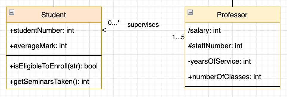
Scope
Type
You can add the data types to attributes and methods, including both the data passed to that method, and the data returned by it. Use a colon followed by the data type. For example: +name: string or +area(radius:float) :double
Define the type of relationship between classes using a connector that has a specific symbol, labels at either end, and either a solid or dashed line.
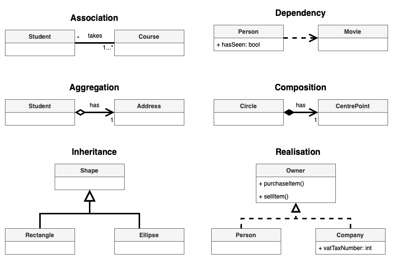
Tip: When two classes are aware of each other, and may use each other’s attributes or methods, place an association with arrows at both ends to indicate a bidirectional association.
Click on or drag the connector you want to use from the UML shape library, then drag each end and drop it onto a class shape on the drawing canvas.
Alternatively, draw a connector from class 1 to class 2 or select an existing connector. Then change its source and target ‘arrows’ from the drop down list in the Style tab of the format panel.
Tip: Drop a connector end on the class name while the outer edge of the class is highlighted in blue - the connector will float around the class as you move it on the drawing canvas.
Connector labels
You can add labels to a connector to further define the relationship between the classes.

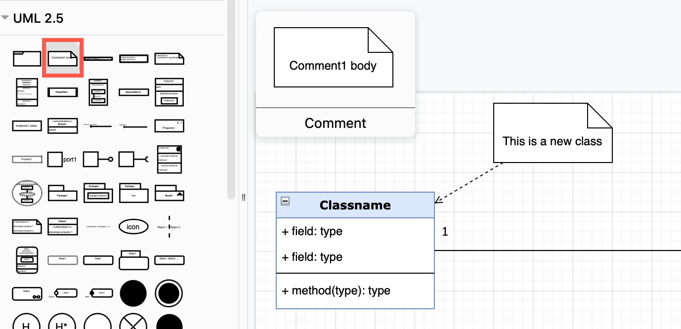
Add a note shape and connect it to a class with a dashed or dotted arrow to include additional information. Use the Comment or Constraint shapes from the UML 2.5 shape library.
For more about UML notation, please refer to the UML 2.5 specification.
To collaborate remotely on a rough class diagram with your colleagues, use the Sketch online whiteboard theme to minimise distraction. Share your cursor in real time with your team when you store the diagram file in Google Drive or Microsoft One Drive.
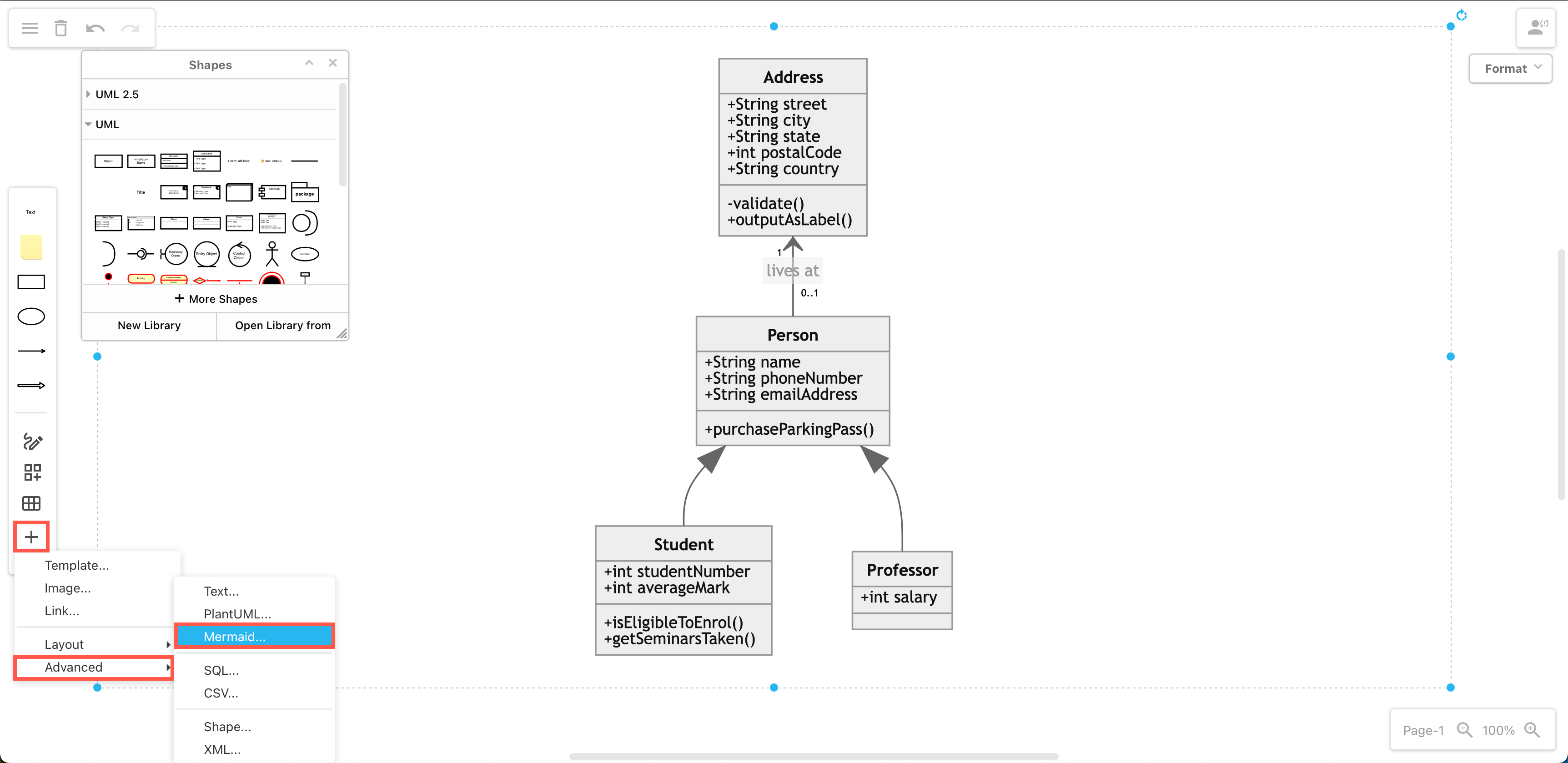
Describe classes and their relationships in Mermaid notation and generate a diagram automatically from the text. Select Arrange > Insert > Advanced > Mermaid from the menu.
Generate a PlantUML diagram in the same way: select Arrange > Insert > Advanced > PlantUML from the menu.
Note: If you are using the Sketch whiteboard theme, click + in the toolbar, then select Advanced to see the Mermaid and PlantUML options.
The UML specification details notation for many different types of diagrams to model the behaviour and data of a system in many different ways.
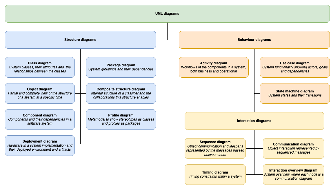
Learn more about the following UML diagrams: